Electric Burner Control Circuit Boards: how they work and how to tell when one is failing
Introduction: The control circuit board works as the brain of an electric burner
Your induction cooktop or electric stove operates by using a control circuit board to regulate power. This small electronic component manages the burner’s temperature control, safety features, and overall operation. When this board fails, the burner may turn off unexpectedly or become uncontrollably hot.
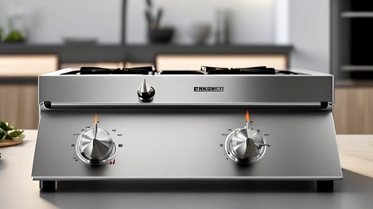
In this article, we will explain how the control circuit board of an electric burner works, what its main components are, and most importantly—how to recognize when your burner board is failing. We’ll also provide practical tips and solutions.
What are the main functions of a control circuit board?
The main functions of a control circuit board in an electric burner are:
- Temperature Control: Turns the burner on and off based on the user-set temperature.
- Power Management: Regulates the amount of power supplied to the burner.
- Safety Features: Prevents overheating, detects short circuits, and shuts down automatically if needed.
- Input Signal Processing: Handles signals from touch controls or knobs.
- Display Control: Updates the digital display with temperature, timer, and other information.
Main Components of a Control Circuit Board
Several important components make up the control circuit board of an electric burner. Let’s examine them:
1. Microcontroller
This is the brain of the system. It receives data from sensors and decides when to turn the burner on or off and what temperature to maintain.
2. Power Supply Unit
Provides power to the burner and supplies the required voltage to other components.
3. Sensors
- Temperature Sensor: Measures the burner’s temperature.
- Current Sensor: Prevents overload by monitoring current flow.
- Voltage Sensor: Measures electrical voltage.
4. Transistors & Relays
These components control the flow of electricity. Transistors amplify small signals into larger currents, while relays act as electrical switches.
5. Capacitors
Store power and help stabilize the circuit.
6. Resistors & Diodes
- Resistor: Limits current flow.
- Diode: Allows electricity to flow in one direction only.
7. Fuse
Protects the circuit by preventing excessive current flow.
How does the control circuit board work? Step-by-step explanation
Let’s walk through how a typical induction burner control circuit board operates:
Step 1: Accept user input
When you set the temperature using the touch control or knob, that input is first sent to the control circuit board.
Step 2: Sensor Data Collection
The board collects data from various sensors, including temperature, current, and voltage.
Step 3: Data Processing and Decision Making
The microcontroller processes the sensor data to determine the required heating level.
Step 4: Power Control
Transistors and relays adjust the current flow based on the microcontroller’s instructions, heating the burner to the correct temperature.
Step 5: Safety Check
Throughout operation, the control circuit board continuously monitors for abnormalities such as overheating or short circuits. If a problem is detected, the burner shuts off immediately.
Step 6: Display Update
The burner’s digital display updates with temperature, timer, and other relevant information.
What are the symptoms of control circuit board failure?
If your electric burner’s control circuit board fails, you may notice several warning signs. Let’s go through them:
1. Burner not working (No Power/No Heat)
- The burner does not produce any heat when turned on.
- The display shows no indication.
- Touch controls or knobs do not respond.
2. Uncontrolled heating (Overheating)
- The burner gets hotter than normal.
- It overheats quickly when left on.
- The area around the burner becomes excessively hot.
3. Strange Noises or Smells
- A burning smell comes from the burner.
- A wet or burnt electrical odor appears when the burner is turned on.
- Unusual noises such as squealing or cracking occur.
4. Random Shut Off/On
- The burner shuts off suddenly while in use.
- It turns off immediately when activated.
- The burner turns on and off without user input.
5. Error Codes on Display
Modern electric burners often display error codes when something goes wrong. Common examples include:
- E1: Sensor issue
- E2: Overheating
- E3: Voltage problem
- E4: Current overload
6. Burner completely dead
- The burner does not respond when turned on.
- No part of the burner functions.
Possible Causes of Control Circuit Board Failure
Several factors can lead to control circuit board failure. Let’s look at the most common ones:
1. Power Surges or Fluctuations
Sudden increases or decreases in current can damage the control circuit board.
2. Overheating
Prolonged exposure to high temperatures can damage the control circuit board.
3. Liquid Spillage
Water or other liquids spilled on the burner can damage the control circuit board.
4. Long Period of Inactivity
If the burner is unused for an extended time, internal components may corrode.
5. Manufacturing Defect
Sometimes, defects in the control circuit board’s manufacturing process cause failure.
6. Power Supply Issues
Problems with the burner’s power supply can damage the control circuit board.
What to do if the control circuit board fails? Solutions and Tips
If your electric burner’s control circuit board has failed, follow the steps below. Some issues can be resolved on your own, while others require professional help. Let’s go through the process in detail.
Step 1: Turn off the burner and disconnect the power
First, switch off the burner and unplug it. Disconnecting power is essential before performing any repairs. Also, remove any liquids or metal objects near the burner. Attempting repairs with power connected can cause serious accidents.
Step 2: Confirm the problem is with the control circuit board
Check the following to determine if the control circuit board is the issue:
- Other burner components: Inspect the heating element, sensors, wires, and connector pins. Replace any damaged parts.
- Power flow: Verify that power is reaching the burner. Use a multimeter to measure voltage. If no voltage is detected, the issue may be with the power supply.
- Fuse and circuit breaker: Check if the burner fuse is blown or if the circuit breaker has tripped. Replace a blown fuse with one of the correct rating.
Step 3: Reset the burner
Sometimes, resetting the control circuit board can resolve the issue. To reset the burner:
- Unplug the burner.
- Wait 10–15 minutes.
- Reconnect the power and turn the burner on.
If the burner restarts and works normally, the issue was temporary. If the problem continues, proceed to the next steps.
Step 4: Check fuses and circuit breakers
Inspect the burner fuse and circuit breaker. Replace a blown fuse or reset a tripped breaker. Use a fuse with the correct ampere rating. If the breaker trips repeatedly, there may be a power supply issue.
Step 5: Clean the burner
Dust or liquid exposure can damage the burner control circuit board. Clean the burner regularly and avoid spilling liquids. Use a soft brush or cloth for cleaning and avoid abrasive materials. If dust accumulates on the control circuit board, use compressed air to clean it.
Step 6: Call a professional technician
If the problem persists after trying the above steps, contact a professional technician. Replacing a control circuit board is complex and attempting it yourself can cause further damage. A technician can diagnose the issue and provide the right solution.
Things to consider before replacing the control circuit board
If the technician determines that the control circuit board needs replacement, keep the following in mind:
- Use original parts: Always use an original control circuit board. Counterfeit or low-quality parts can reduce performance and cause additional problems.
- Check warranty: See if the burner is still under warranty. Some warranties cover repairs or replacements.
- Compare prices: Compare prices from different stores. The same part may be available at varying costs.
- Installation charges: Ask about technician installation fees. Sometimes, installation costs more than the part itself.
Control circuit board replacement cost
Replacement costs depend on the burner’s brand, model, and local repair shop. Below are approximate cost estimates:
| Brand | Model | Replacement cost (USD) | Installation Charges (USD) |
|---|---|---|---|
| Bosch | Serie 4 | $80 – $120 | $15 – $25 |
| LG | K7M5 | $75 – $105 | $12 – $20 |
| Samsung | NZ65K | $65 – $95 | $10 – $18 |
| Panasonic | KZ-PH30 | $90 – $130 | $20 – $30 |
Note: The above costs are approximate and may vary depending on local markets and stores.
What to do after replacing the control circuit board
After installing the new control circuit board, keep the following points in mind:
- Check the burner: Test the burner to ensure it works properly. Verify operation at different temperature settings.
- Follow instructions: Refer to the burner’s user manual to learn how to use the new control circuit board.
- Routine maintenance: Clean the burner regularly and address issues promptly.
- Check warranty: Save the warranty for the new control circuit board and report any issues within the warranty period.
Conclusion
The control circuit board of an electric burner acts as its brain. If this small but critical component fails, the entire burner may stop working. In this discussion, we’ve covered how the control circuit board functions, its failure causes, symptoms, and solutions.
If your burner’s control circuit board fails, first disconnect the power and diagnose the issue. Try troubleshooting yourself, but if the problem persists, contact a professional technician. DIY repairs can cause further damage and may be unsafe.
Take care of your burner by keeping it clean and addressing problems quickly. Use high-quality parts and consider replacing the burner if it’s old. A well-maintained electric burner makes cooking easier and more enjoyable.

About the Author
Hi I am an Engineer I have passed my diploma in Engineering in 2007. Academically I have studied about home appliances and various motors and machineries. In 2012 I have started my blogging and learned a lot of things about home appliances especially washing appliances, washing and cleaning related products, and eequipments. In 2019 I have started my blog https://appliancesky.com to provide my research and experience with my fan and followers.